![<?echo $_SERVER['SERVER_NAME'];?>](/template/twentyseventeen/skin/images/header.jpg)
Vortex flowmeter because of its simple structure, stable function, low pressure loss. Wide range of features such as the wide range of scale has been widely used in liquid measurement. The principle is that when the liquid passes through the vortex in the pipeline, the frequency of the vortex oscillation is proportional to the flow velocity. In vortex flow transmitters, piezoelectric crystals or differential capacitors are used as sensors to expand, filter, and drive the detected weak oscillating signals, and then output pulse signals whose frequency is proportional to the instantaneous volumetric flow rate. Cheng He type printed circuit board, commonly known as the expansion board. This type of transmitter is suitable for divergence. Each transmitter is equipped with a flow totalizer based on frequency detection. In recent years, many companies have gradually adopted the instrument distribution management mode. This requires that the flow signals from multiple measuring points be consistently changed to 4-20 mA, and then sent to the accounting machine to be gathered and managed, thus presenting the two-wire 4-20 mA. Vortex flow transmitter, which is connected with a change board behind the original expansion board. The change board is composed of f / V and V / I circuits. The frequency signal output from the expansion board is changed to 4-20mA output.
Influence of nonlinear coefficient of appearance
The non-linearity of the sensor output signal is the most important factor restricting the accuracy of the vortex flow transmitter. Nonlinearity causes the coefficient K of each flow interval to be not a constant. The appearance coefficient is defined as the number of rushes and rushes per cubic metre of flow. The transmitter's nonlinear error bound is (Kmax-Kmin)/(Kmax+Kmin)×100%. In general, the accuracy of a constant transmitter that outputs a pulsed frequency signal is nominally up to 1-2. Regarding the current output in vortex transmitters, due to the participation of f / V links in the circuit, although the f / V switching circuit based on RC charge and discharge has high resolution, the linearity and stability are not satisfactory. The need for precision change.
2 The mechanism and role of proofreading
Take a f500mm capacitive vortex flowmeter produced by Jiangsu Xuhui Instrument Automation Co., Ltd. as an example. The transmitter inspection data is listed in Table 1.
Table 1
Flow/Nm 3 ·h -1
Fundamental error d I (%)
Test point repeatability Eri (%)
150
0. 820
0. 169
300
0.169
0.226
450
-0.271
0.143
675
-0. 694
0.160
800
-0. 302
0.217
Each flow was measured 3 times and averaged. From the data in Table 1, it can be seen that the maximum error of this table is 0.82, which can only be rated as Level 1. It is expected that the accuracy of the appearance will be improved if the 5 point appearance constant can be given proofreading at the corresponding point. It should be noted that the improvement of the appearance accuracy level is based on the smaller roots of the repeated errors of verification, and the repeatability is better than the characteristics of the vortex flowmeter. On the other hand, if the repeatability is not good, the nonlinear proofreading will lose meaning, and the effect of the nonlinear proofreading will be constrained by repeated mistakes. The maximum repetition error of this table is 0.266%. After a non-linear proofreading, the accuracy is expected to reach 0.5.
There are many factors that affect linearity, such as data, configuration, and technology, as well as the quality of the enlarged circuit, which can come from the detection components. The integration of the transmitter's own intelligence, signal conversion and proofreading is a shortcut to improve its accuracy.
3 intelligent two-wire 4-20mA vortex flow transmitter
3."> Block Diagram
The structure diagram of the 2-wire 4-20mA vortex flow transmitter in charge of the plan is shown in Figure 1.
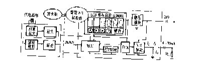
Fig.1 Block diagram of two-wire 4-20mA vortex flow transmitter
The circuit structure of the original expansion board does not change at all. Only the micro power consumption is improved, and a change board is added to this foundation. Two circular boards are fixed on both sides of the cylindrical metal shell of the transmitter, and the signal and the power line are connected to the connector. The general-purpose two-wire system is adopted, and all components including the expansion board are micro-power type, so that the zero current does not exceed the requirement of 4 mA. MCU selects the MCS-51 series of 89C2051. The internal two counters/timekeeping devices T 0 and T 1 are set to count and work mode to perform high-precision detection of the pulse frequency from the expansion board. The result of the operation passes through 10 bits. The resolution serial D/AMAX504 manipulates the output current. The accuracy of the two intermediate processes of frequency detection and D/A change is better than 0.1%.
3.2 Proofing operations
The instantaneous flow at point i of the transmitter is given by:
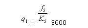 (1)
(1)
In the formula: Ki appearance coefficient, ambition condition is a constant.
In Fig. 1, the current I iL flowing through the sampling load resistor R L is equal to I 0 +I i , during which I 0 is a zero point current and is adjusted to 4 mA. Ii is controlled by D/A. Without considering calibration, there is the following positive linear relationship. set up:
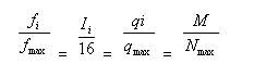 (2)
(2)
Where: N is the value that is input to D/A when the corresponding output current Ii.
But in general, the appearance constant Ki is not a constant. The general practice is to take the average K as a reference within the measurement scale. Set the actual appearance constant of each flow point as Ki, and define the proof factor as mi
Mi=K/Ki
So, practice instantaneous traffic
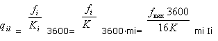 (3)
(3)
The above formula indicates that you only need to know the proof factor mi and multiply the current with the current Ii calculated on the basis of the linearity of the current, and you can obtain and verify the flow rate.  The corresponding current. Each mi is obtained when the transmitter is calibrated. After the proofreading current mi Ii obtains the data N and inputs it to the D/A to control the output current, the proofreading intention can be reached. In summary, in the two-wire transmitter, the proofreading of the output current is a non-linear proofreading of the external table coefficient.
3.3 Proofreading completion strategy
In theory, only with a 5-point proof factor, mi, and then through the accounting and analysis of the system, it is possible to obtain a curve function analytical formula of the proofreading factor, and proofread accordingly. However, the difficulties of detailed completion are as follows: (1) The nonlinear shape of the external coefficient of the vortex flowmeter has divergence and is not suitable for fitting with a single-form curve; (2) The smart appearance is not suitable for inputting a polynomial coefficient with a large cross-value. The hardware and software planning of smart transmitters should be sufficient considering that they can be used for verification procedures and on-site operation requirements, but also in line with the style of smart appearance, and strive to arrive at the intent, input method, and algorithm with at least the input data volume. Simple and useful.
3.3."> Input of Adjustment Factor bi
make
Mi=1+0.001bi; I=1,2,3,4,5
The bi-boundary is the adjustment coefficient, which is 2-digit decimal. The use of bi instead of mi is due to the simple input of the former, and the less data used, occupying at least the memory of the MCU. In planning, let bi total be greater than 0, thus avoiding the inconvenience of input negative number (down current). When the value of bi changes from 00 to 99, the maximum (up to 9.9%) fluctuation of current output (or K value) can be achieved. This scale has satisfied the general needs. In FIG. 2, the line AB shows the linear relationship between the output current of the smart board and the input frequency. To ensure that the total of bi is greater than 0, mi is always greater than 1. Before the calibration, the current at each flow point should be decreased before the full range parameter is adjusted. Even if the low interest rate of the straight line AB is reduced, the space for the pull-up of the current during the proofreading of the entire region is reserved, and the total amount is at the same time. The b5 is specifically designed for pull-up proofreading to ensure correct back to 20mA after proofreading at full flow. The manual operation software is planned in the transmitter. Press parameter setting key “S†to enter the parameter setting correction status. The appearance and keyboard can be seen in Figure 1. This input method ensures the convenient placement of bi. When on-line inspection is performed, the corresponding bi can be adjusted according to the real-time calibration flow. When the flow is adjusted to the appearance and the flow is equal to the real-time calibration flow, press the write key to write the bi value into the E 2 PROM reserve; it can also be based on each check after verification. The error between the output current corresponding to the actual flow rate and the current output in real time is calculated, and each point bi is calculated and placed.
3.3.2 Full Scale Calibration
When the output currents of the five flow points are calibrated, the five-point and zero-segment five-segment break lines of 1-5 can be used to indicate the current output curve after the transmitter is calibrated, as shown in FIG. 2 . The program calibrates the traffic point according to linear interpolation.

Figure 2 Linear interpolation calibration proof output current
In Figure 2, f1, f2, f3, f4, and fmax are compared in order to determine which section of the polyline to collate. When it is determined as line j, the adjustment factor bx of the flow point is calculated according to equation (4):
Bx=bj+(bj-bj-1) 
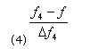
On the broken line 1, b 0 is 0, because the zero has been adjusted beforehand, the proofreading amount is naturally zero. Figure 2 shows the current required to calibrate the corresponding frequency f  ? , according to formula (4) accounting bx formula is
Bx=b4+(b4-b4-1)
4 Conclusion
The intelligent two-wire 4-20mA vortex flow transmitter can also realize the remote flow or output current, output frequency of the remote place or cycle; online browsing, setting and storage of the following parameters: full scale, 5 points adjustment coefficient, Filter output damping coefficient and zero and span adjustment coefficient. In addition to the level and level of accuracy with which it can effectively improve its appearance, it also has the advantages of easy operation, convenient commissioning and general purpose. It is developed in response to DCS user needs and the next step is to get closer to the HART bus.
Mini Manual Hand Lift is a lifting platform for transporting small items, and similar to the function of the forklift truck. Electric Manual Lifts has the advantages of small size, flexibility, strong maneuverability, and easy operation.
Only has the most basic handling function, pure manual control, the volume is small, the weight is light, the lifting platform does not have the lift function. More for simple goods handling.
By means of manual operation, the transportation of small amount of goods in small place is realized by hydraulic or electric driven way.
Hydraulic Trolley Lift Specifications Table:
|
Model |
Lift Capacity (kg) |
Max. Height (mm) |
Min. Height (mm) |
Platform Size (mm) |
Weight (kg) |
Wheel Dia. (mm) |
|
GTT-15 |
150 |
720 |
220 |
700*450*36 |
46 |
Φ100*25 |
|
GTT-30 |
300 |
900 |
210 |
855*500*50 |
80 |
Φ125*40 |
|
GTT-35 |
350 |
1300 |
355 |
910*500*53 |
105 |
Φ125*40 |
|
GTT-50 |
500 |
900 |
285 |
815*500*53 |
115 |
Φ125*40 |
|
GTT-70 |
700 |
1500 |
445 |
1220*610*53 |
195 |
Φ125*40 |
|
GTT-75 |
750 |
990 |
420 |
1000*510*55 |
125 |
Φ147*50 |
|
GTT-100 |
1000 |
990 |
380 |
1016*510*55 |
140 |
Φ147*50 |


Application Area:
The Hydraulic Trolley Lift is mainly used in warehouses, workshop and other places where people need to lift medium weight goods. Hydraulic Single Scissor Lift Hand Pallet Truck is the ideal choice for super markets, malls and logistics warehousing companies.
If you have any questions, please contact with us directly. Hydraulic Trolley Lift are produced with High Quality and Good Appearance. Welcome you can visit our Factory. For inqury, Please send mail directly to us.
Hydraulic Trolley Lift
Hydraulic Trolley,Hydraulic Lifting Trolley,Hydraulic Trolley Lift,Lifting Trolley
Jinan East Machinery Co.,Ltd. , https://www.jneastmach.com