The application of E+H non-contact single-probe ultrasonic level detector in the iron alloy silo of Panzhihua Steel's RH-MFB vacuum processing plant was introduced. The principle, functional characteristics and installation requirements of the detector were described. Practice has proved that the detector has the advantages of simple installation, low maintenance, low failure rate, high accuracy (with a resolution within ±5mm), simple calibration, safety and reliability, and has the promotion value.
[Keywords] level measurement; non-contact; ultrasonic; matrix 1 Introduction Panzhihua Iron and Steel RH-MFB vacuum processing device is mainly for the removal of molten steel gas, inclusion, desulfurization, decarburization, treatment process need to add alloy adjustment steel composition, so set There are 14 alloy silos. In order to know how much the alloy material level in the hopper is, and to control the alloy addition speed in time, it is necessary to test the alloy material level. Because the measured medium of the silo is coarse and loose solid, the ultrasonic level detector has non-contact, corrosion-resistant, material height measurement suitable for large storage tanks in various level detection instruments, and can affect the measurement accuracy. Correcting and outputting various standard signals according to user requirements has been widely used in the production process. Therefore, the non-contact single-probe ultrasonic level detector of E+H company was selected.
2 Principle of Ultrasonic Detection The high-power piezoelectric ceramic ultrasonic probe emits a focused ultrasonic pulse that passes through the air and reaches the surface of the measured medium. This pulse is reflected back to the probe in whole or in part. The probe is both a transmitting device and a receiving device. It converts the received reflected wave into an electrical signal. According to the time the pulse is sent and received, it is proportional to the distance between the probe and the surface of the medium. The distance D can be calculated by the following formula:
D=C·t/2(2—1)
C—sonic speed; t—sound transmission time.
Let the distance from the probe to the lower part of the silo be B, then the silo height H is: H=LD=LD=LC·t/2, as shown in Figure 2-1. B is a blind spot.
Since the temperature change has a great influence on the speed of sound C, the speed of sound must be compensated by the temperature sensor and its compensation circuit. The compensation can be performed according to the following formula; C = 331.45 + 0.61T. For each measurement time t of the measurement system, a temperature factory value is used at the same time, and then the sound speed C is calculated according to the above formula, and the equation is entered into the formula (2-1). Distance D.
3 system composition and function characteristics Ultrasonic detection system components: ultrasonic probe DU41C, level transmitter FMU677, communicator UV260Z. 14 silos are equipped with 14 sets of ultrasonic detection systems. The transmitter adopts bracket mounting, uses shielded cable, and the output signal is used as the analog input of Siemens PLCS5-155U. The relay contact signal is connected with the digital input module of PLC. It has a high and low limit alarm function, and the detection result is displayed on the operation station. The composition is shown in Figure 2-1.
3.1 Ultrasonic probe The probe model is DU41C, corrosion-resistant, with automatic echo frequency control, suitable for continuous, non-contact level measurement. Operating temperature -20 °C ~ +60 °C, in order to compensate for the error caused by temperature changes, in the ultrasound probe is also equipped with a temperature probe for temperature change correction. The probe can measure 20m deep liquid level, 10m high loose solid material level. The operating frequency is about 29kHz, and the blind area is about 0.9m.
3.2 Ultrasonic Transmitter Transmitter FMU 677 is used as the process variable of the control system to detect the level of material in the silo. The transmitter supplies power to the probe. The probe sends back an analog signal of the measured value. The transmitter converts this signal into a material level indication and sends it to the analog output.
All functions of the transmitter, including analog output and relay transition points, can be entered using the work matrix table. Each value in the matrix is ​​displayed with the vertical (V) and horizontal (H) coordinates. The work matrix must be called for the measurement point and system calibration. The fault diagnosis information can also be found in the matrix table and can be changed with the Communicator UV260Z. Feeder front panel input, easy to operate. The measuring system has six operating modes that make it suitable for measuring liquids or loose solids. The measured medium of the system is a rough, loose solid, so the working mode 5 is selected. For containers that are not proportional to volume and material level, manual linearization translates the level measurement into a volume measurement.
The analog output of the transmitter can convert current output 0 (or 4) to 20mA, and the other channel can convert voltage output 0 (or 2) to 10V. Internal filters are used to smooth analog output fluctuations. If the transmitter's self-tracking circuit finds a fault or alarm, the current and voltage outputs can take a specific value, at which point the relay operates with the high and low limits of the analog output. Each of the transmitter's two independent relays, each with voltage isolation, makes contact changes based on the size of the measurement. Each limit switch can adopt the minimum/maximum fail-safe mode. The lag time of the limit switch can be freely selected. This is the point when the relay turns off when the material level returns to normal.
For potential or intermittent echo interference inside the container, fixed target suppression can be used to prevent spurious echoes; or envelope curve statistics, calculate the average of all envelope curves, adjust the appropriate parameters to suppress intermittent interference; if the maximum level The blind interval has a fixed part, increasing the blind zone distance can eliminate the echo produced by it.
In addition, the transmitter can monitor all the loops from the probe to the output and indicate the fault signal issued by the alarm relay (alarm light is on, and transmits the fault signal). In addition, the simulation method can be used to check whether the system is operating normally, which helps the staff to correct the fault in time.
3.3 Installation Requirements One of the prerequisites for accurate ultrasonic measurement is the correct positioning and mounting of the probe so that the detector can be used normally and measurement errors can be reduced. The following points should be noted when installing:
1) The installation should be perpendicular to the surface of the media, leaving a dead zone. The media will not touch the probe when the container is spilled.
2) To measure the solid material elbow in the silo, consider that the solid material is not flat at the interface. Generally, the material at the feed port is higher than the periphery of the storage tank, so the probe should be installed at a position where the average height of the reaction material can be measured. Do not install the probe at the top center of the silo.
3) The ultrasonic probe has its sound wave pointing angle. Any object within the transmission beam range, including the container and the tank wall, will reflect the interference echo and produce measurement error. Therefore, the probe installation position should not be too close to the wall. In practical applications, since the lower part of the silo is conical, the acoustic wave will be reflected near the center of the material outlet funnel (even if the hopper is empty), so adjust the angle of the probe as far as possible away from the container wall, baffle and material inlet.
4 Conclusion The ultrasonic level detector has been operating normally since the operation (measurement resolution within ± 5mm), has achieved greater economic benefits, it is worth promoting. Its advantages are mainly reflected in the following aspects:
Because the ultrasonic level meter has no movable parts and no mechanical wear, it is easy to install and easy to implement. Non-contact measurement and maintenance are less, and the failure rate is reduced. The calibration is simple, high precision, safe and reliable.
The system's upper and lower limit alarms are accurate, ensuring timely addition and subtraction of materials; accurate measurement and intuitive display, enabling operators to effectively control alloy addition speeds, improve work efficiency and accuracy, and create conditions for continuous casting to produce high-quality alloy steels. .
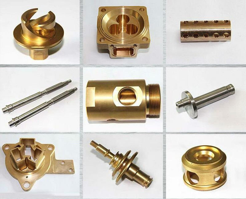
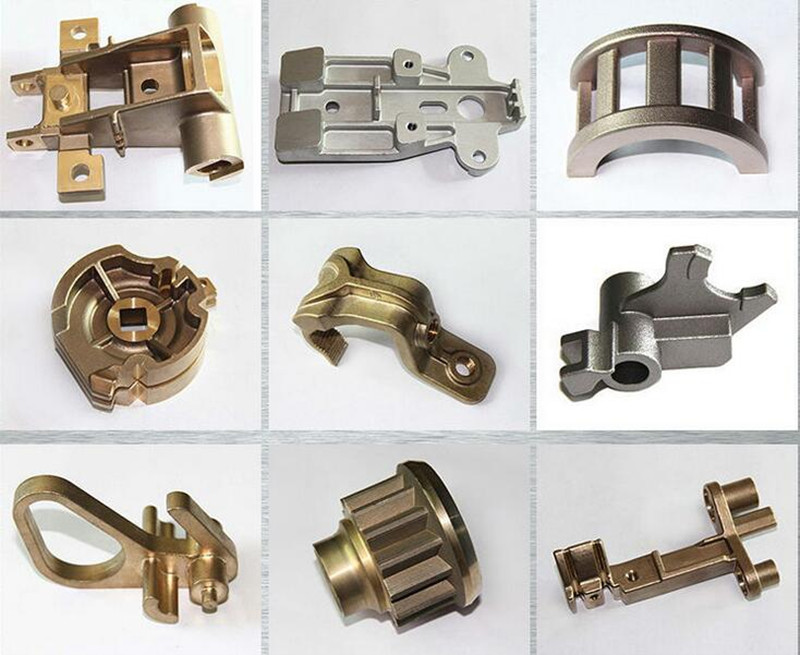
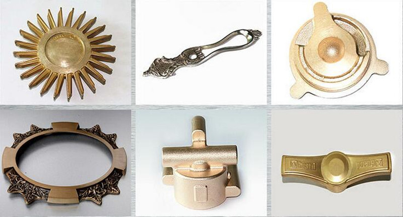
OEM Brass Forging Parts
| Description: | Brass Forging |
| Material: | Forged brass C37700 or CW617 |
| Process: | Hot Forging, lathe machining |
| Finish: | sand blasting |
| Key tolerance: | +/-0.10mm |
| Application: | plumbing fittings |
| Origin: | China |
| Note: | Above item is for your reference only, not for sale; We only produce custom parts per customer's drawing or sample |
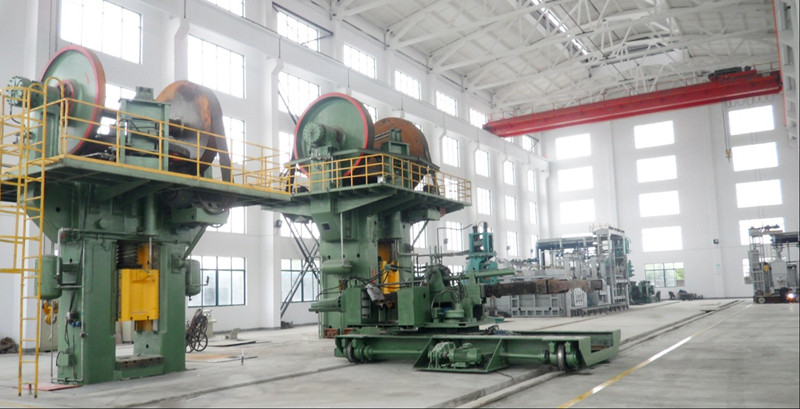
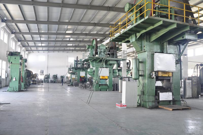
Our forging plant has large-scale forging machines of 10 sets including one 4000 tons free forging hydraulic press. We have more than 50 high qualified technicians. Our forging scope limit is 1-40000 kg and our production capacity is 8000 tons a year. The application material includes all iron, steel, alloy steel, stainless steel, hear-resisting alloy steel, duplex stainless steel and other special materials.
Brass Forging
Brass Forging,Brass Forged Fitting,Brass Long Forged,Forged Pipe Fittings
Hebei Mingda International Trading Co.,Ltd , http://www.mingdacasting.com
![<?echo $_SERVER['SERVER_NAME'];?>](/template/twentyseventeen/skin/images/header.jpg)