HDZK Vacuum Switch Vacuum Tester Test Principle

Test principle
This instrument adopts magnetron discharge method for measurement. Pull the two contacts of the vacuum switch arc extinguishing chamber a certain distance, apply the electric field pulse high voltage, place the arc extinguishing chamber in the solenoid coil or place the new electromagnetic coil outside the arc extinguishing chamber, and apply a large current to the coil. Therefore, a pulsed magnetic field synchronized with the high voltage is generated in the arc extinguishing chamber. In this way, under the action of a pulsed strong magnetic field and a strong electric field, the charged ions in the arc extinguishing chamber spirally move and ionize with the residual gas molecules. The ion current generated is approximately proportional to the residual gas density, ie, the degree of vacuum. For different vacuum tube models (tube types), due to their different structures, under the conditions of the same contact opening distance, the same vacuum degree, the same electric and magnetic fields, the magnitude of the ion current is also different. Correspondence curves between vacuum degree and ion current of various tube types can be calibrated through experiments. When the ion current is measured, the vacuum of the tube can be obtained by querying the ion current-vacuum curve of the tube.
When testing the vacuum of an arc extinguishing chamber by a conventional magnetron discharge, in order to improve its test sensitivity, it is necessary to remove the arc extinguishing chamber from the circuit breaker and place it in a solenoid pipe. In this way, when the arc extinguishing chamber is reinstalled, the mechanical parameters need to be adjusted, the workload is large and professionals are needed. The use of a new type of magnetron coil can surround the arc extinguishing chamber from the side, so that it is not necessary to dismantle the arc extinguishing chamber. The use of a single-chip microcomputer for synchronous control and data acquisition processing improves the field test sensitivity of the arc extinguishing chamber vacuum.
Fives. How the instrument works
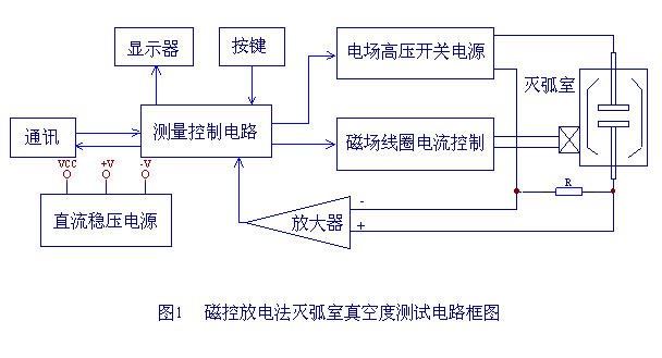
The block diagram of the vacuum tester is shown in Figure 1.
1
The whole machine is composed of measurement control circuit, electric field high voltage generation circuit, magnetic field coil current control circuit, communication, printer, liquid crystal display circuit and so on. The working process is as follows: a command is issued by the measurement control circuit, the magnetic field capacitor is charged by the switching power supply, and monitored by the control circuit. When the voltage on the magnetic field capacitor reaches a predetermined value, the control circuit sends two control signals to control the output and The conduction of the magnetic field coil current causes the arc extinguishing chamber to be in a state of a strong electric field and a strong magnetic field, and the arc extinguishing chamber starts to discharge, generating an ion current I, as shown by the curve I in FIG. 2. The current is input to the single-chip microcomputer through the sampling resistor R and the pre-processing circuit, and finally the measured vacuum value is displayed on the liquid crystal display after calculation.
Second, the main features
1. Quantitative measurement of the vacuum degree in the arc extinguishing chamber of various types of vacuum switches;
2. There is no need to disassemble the vacuum switch during field measurement;
3. The test results are accurate and reliable;
4, LCD Chinese characters display, the operation is more simple and convenient;
5. Test data can be saved, printed and viewed;
6. The instrument has an RS232 communication interface, which can be connected to a computer to realize various functions such as vacuum degree-ion current curve downloading, life estimation, etc .;
7. The instrument is light in weight and easy to carry;
Third, the performance indicators
1. Power supply: AC220V + 15%, 50Hz;
2. Measuring range: 10-5 ~ 10-1Pa;
3. Electric field voltage: 18KV;
4. Magnetic field voltage: 1600V;
5. Instrument accuracy: 5%;
6. Operating environment: -10 ℃ ~ 40 ℃;
7, amateur size: 460mm × 335mm × 330mm.
8. Host weight: 12kg;

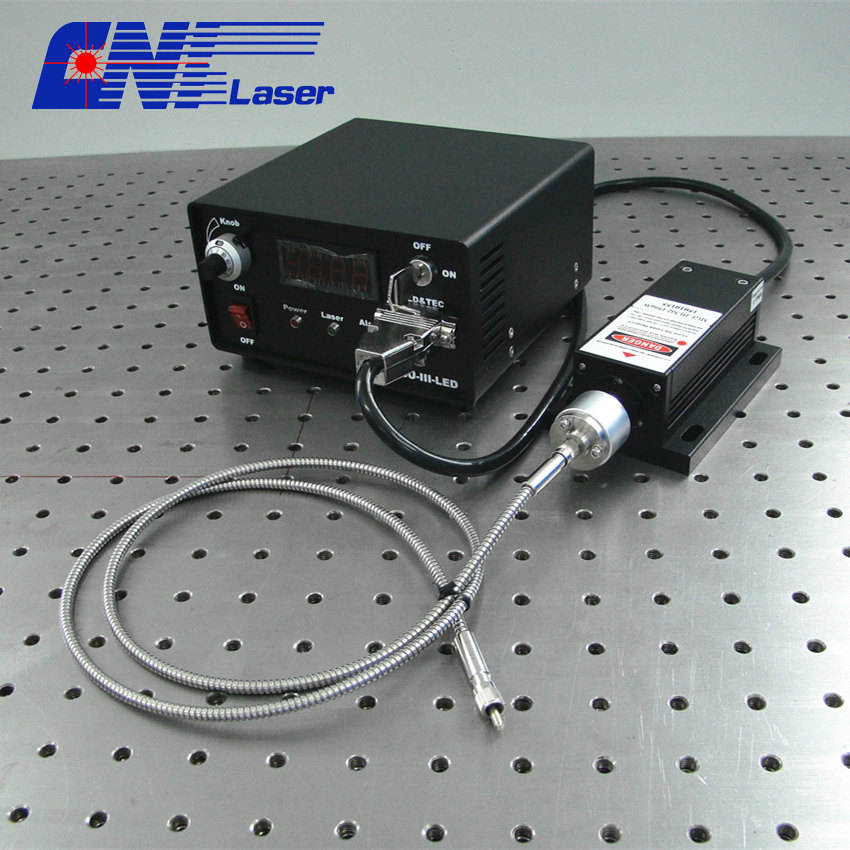
All series CNI Laser modules can be fiber coupled with different core diameter MM fiber or SM fiber. You have  to refer to the detailed specs of each laser modules (such as power, stability, noise, size, etc) to decide which one is suitable for your application. We would like to do the coupling job for you.

The collimator of Fiber Coupling Laser is designed to connect to the end of FC/PC or SMA905 connector and contains an AR-coated spherical lens. The distance between the spherical lens and the tip of the FC-terminated fiber can be adjusted to compensate for focal length changes, or to re-collimate the beam at the specific wavelength and distance of interest.

Fiber Coupling Efficiency Chart (Connector: SMA905 or FC)

Laser Type

Fiber Coupling Efficiency

FC for SM fiber ,FC/SMA905 for MM fiber

SM Fiber

4~9 µm

MM Fiber

≥50 µm

MM Fiber

≥100 µm

MM Fiber

≥200 µm

MM Fiber

≥400 µm

DPSS Laser

TEMoo

>40%

>70%

>75%

>80%

>90%

Multi transverse mode

>20%

>60%

>70%

>80%

>90%

Diode Laser

TEMoo

>30%

>60%

>75%

>80%

>90%

Multi transverse mode

Low

>30%

>65%

>75%

>85%
fiber coupling laser


Fiber Coupling Laser

Fiber Coupling Laser,Fiber Coupled Laser,Infrared Fiber Laser System,Diode Laser Module

Changchun New Industries Optoelectronics Technology Co., Ltd. , https://www.lasersciences.com

Posted on