![<?echo $_SERVER['SERVER_NAME'];?>](/template/twentyseventeen/skin/images/header.jpg)
I. Status Quo of the Project 1.1 Datang Leiyang Power Plant was formerly known as Xiangyang Power Plant in Hunan Province. It was established in 1983 and was officially built in 1987. In 2002, the State Power System Reform established five power generation group companies nationwide. Therefore, Xiangyang Power Plant in Hunan Province was attributed to China Datang Corporation and was renamed as Datang Xiangyang Power Plant. It is a wholly-owned subsidiary of Datang Corporation. Puyang Power Plant is located in Liyang City, Hunan Province, the hometown of ancient papermaking inventor Cai Lun (belonging to the jurisdiction of Hengyang City). It is located on the banks of the Surabaya River. The plant covers an area of ​​260 hectares, surrounded by water on three sides, and is supported by mountains. Provincial "Garden Factory". In the first phase of the project, two sets of 200,000 kilowatts of domestic coal-fired units were put into operation in 1988 and 1989 respectively; in the second phase of expansion, two 300,000 kilowatts of units were put into operation in December 2003 and June 2004, respectively, and they were the first in Hunan. Million-grade thermal power plant. At present, three phases of expansion projects are being prepared.
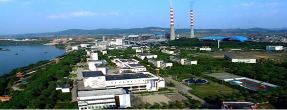
Figure Tangshan Power Plant Panorama Puyang Power Plant 210MW boiler feed water system consists of two sets of 5500kW full capacity feed pump, front pump and load regulating valve. Under the normal operating conditions of the system, the feed pump before the transformation is operated by one train and one standby power frequency mode.
In response to the demand for the energy-saving renovation of the feed pump of Datang Yuyang Power Plant, our company cooperated with Datang Xianyi Energy Saving Technology Co., Ltd. to carry out frequency conversion transformation of No. 1 unit No. 1 feed pump of Datang Fuyang Power Plant. Including liquid couple, oil station, front pump, inverter cooling and so on.
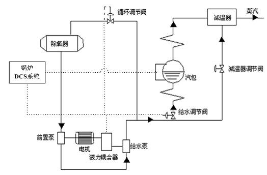
1.2 Water supply system refers to the boiler's water system, which continuously supplies boiler water to ensure normal water circulation. The water pump raises the pressure of the deaerator and sends it to the high-pressure heater. After passing through the water supply console, it enters the economizer of the boiler. The economizer feeds the heated water and sends it to the drum. The down tube distributes the water from the drum to water cooling. Each lower wall of the wall absorbs the radiant heat of the high-temperature flame (flue gas) of the hearth and turns the water into a steam-water mixture. The steam-water mixture enters the steam drum for steam-water separation. The separated water continues to circulate in the water, and the separated saturated steam enters the ceiling. Superheater. The figure on the right shows the schematic diagram of the water supply system:
1.3 Alternatives to the modification of the feed pump 1.3.1 The hydrodynamic coupling is not dismantled (1) The coupling is not removed. During frequency conversion operation, the position of the coupling is opened to the maximum and the coupling is equivalent to that of a coupling.
(2) Since the main oil pump is coaxial with the motor, after the frequency conversion is adopted, the oil pump pressure and oil quantity are insufficient after the motor speed is reduced. The oil pressure required by a power plant pump is not less than 0.25 MPa, and the lubricating oil quantity is not less than 360L. /min; The working oil pressure is not lower than 0.25 MPa, so to meet the oil supply of the oil pump, configure the oil station separately. Dismantling of the primary fluid coupling master oil pump, the specific contents include the transformation of the oil pipeline of the oil station, the basic production and installation of the oil station, the connection of the oil pipeline to the main oil pump impeller of the fluid coupling and its transformation.
(3) Configure the oil station: Configure the oil pump and auxiliary oil pump according to the oil quantity and the oil pressure demand, and run the pump fault trip and the chain standby pump starts. The oil station also needs to configure an electrical control box that meets the oil pump control requirements, oil temperature, oil pressure, oil quantity detection device and other accessory accessories, etc. The detection signal can output 4-20mA signal.
(4) When the inverter is faulty or overhauled, it is switched to the power frequency operation by the inverter bypass. At this time, it still follows the original mode of operation, with liquid coupling speed control.
1.3.2 Dismantling the fluid coupling scheme After the frequency conversion modification on site, instead of the original liquid coupling speed control method, due to the various drawbacks of the fluid coupling itself, taking into account the stability of long-term operation, it is recommended to remove the fluid coupling.
(1) This modification program replaces the fluid coupling of the feed pump with a speed increasing gear box, and the feed pump motor is operated with a frequency converter. The scope of supply needs to increase a set of speed-increasing gearboxes (including input and output couplings; the speed increaser box is installed between the motor and the feedwater pump). Since most of the power plants have backup feed pumps, when the frequency conversion is withdrawn, the standby pump can be started (Liquid Speed ​​Control), so there is no need to increase the soft-up device after the liquid couple is removed. The engineered part needs to solve the connection problem between the motor and the pump after the liquid coupler is disassembled and the lubricant system of the motor.
(2) For a situation where a very few power plants (such as a Guangzhou power plant) do not have a backup pump, when a frequency converter comes out of operation, it may be considered to meet the boiler feedwater demand by increasing the feedwater volume of another feedwater pump. With the water supply to reduce the load, if the water supply requirements can not be met, then one feed pump will be switched to the power frequency operation, another frequency conversion pump will be increased to the power frequency, and the jellyfish tube valve will be adjusted to ensure the stable operation of the system (this part needs According to the boiler load and the valve and inverter joint adjustment).
(3) For the power plant does not have a backup pump, remove the motor starter after the liquid coupler, consider the configuration of the soft starter.
(4) For the condition that the power plant does not have a backup pump, a one-by-one automatic bypass scheme is recommended when the frequency converter is reformed.
1.3.3 Connection problem between motor and feed pump after the liquid coupler is removed
Method 1: Move the motor forward (1) The steel base is to be used as the base of the motor. The base of the base is uniformly distributed with six foot bolts, and secondary grouting of the concrete is required.
(2) In order to ensure the safety of the equipment after it is put into operation, it is necessary to re-customize the friction plates directly connected to the load after the motor is displaced;
(3) The six foot holes are formed by drilling, and the foot bolts are epoxy resin casting and fixing process;
(4) After the foundation is completed, the dynamic balance test of the motor needs to be performed again.
Method 2: The motor base is not moving, and the long shaft connection is used. Since the motor base is moved forward in (Method 1), the construction period is longer and the project volume is larger. It is learned from the site that a gear box has been added between the motor and the feed pump ( The width of the gearbox is about 1500mm, while the installation size of the on-site hydraulic coupling is about 2500mm, so you can consider adding a soft or rigid shaft about 1m long between the motor and the gearbox (if the distance is short, you can Use) Connecting, the connecting shaft is recommended to be installed between the motor and the gearbox. Do not install between the gearbox and the feedwater pump. Because of the low speed on the motor side, the disturbance of the shaft will be smaller. The advantage of this solution is that there is no need to change the installation position of the motor again, the project volume is small, and the construction period is short.
Puyang Power Plant chose to retain the solution of the liquid couple.
Second, the feed pump and motor parameters are introduced Table 1 Pre-pump parameters:
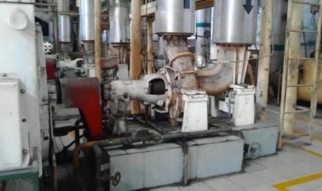
Figure 3: Front pump site photo Table 2 feed pump parameters:
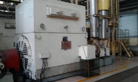
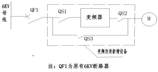
Figure 6: Schematic representation of main circuit conversion
(1) Retain the control logic of the existing DCS system for the #1 electric feed pump motor and its secondary line, and add the new frequency conversion speed control system into the DCS system of the power plant.
(2) Under normal conditions, the 6kV power supply is passed through the circuit breaker QF1, the isolating switch QS1 to the high-voltage frequency conversion device, and the output of the frequency conversion device is sent to the motor via the isolating switch QS2, and the motor is frequency-converted. The frequency converter accepts the speed control signal of the DCS regulator to adjust the speed of the water pump to meet the requirements under different loads.
(3) When the inverter fails to run, the disconnectors QS1 and QS2 are disconnected, the disconnector QS3 is closed, and the electric feed pump is running at a frequency. The functions of the isolation switches QS1 and QS2 are: When the inverter performs maintenance, there are obvious break points to ensure the safety of the maintenance personnel. In the non-inverter maintenance period, the two isolation switches are in the closing state.
(4) QS2 and QS3 cannot be closed at the same time, and they are electrically interlocked to ensure the safe operation of the equipment.
(5) Copper bars are used for electrical connection between the bypass cabinet switches and a live display is also installed.
(6) The secondary electric panel of the bypass cabinet has terminal contacts for the position of the knife gate, and each knife gate provides at least 4 normally open 4 normally closed auxiliary contacts.
(7) There are power frequency and inverter operation position indicators on the bypass cabinet body.
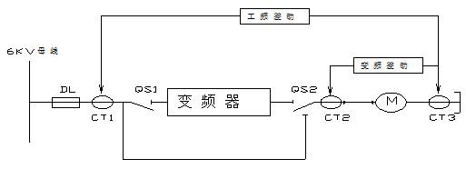
3.3 Protection configuration A set of TA (800/5) is added at the output of the inverter, and the differential protection under variable frequency conditions is established with the feed pump neutral point TA. The power frequency is still operated from the original 6kV switchgear TA. The feed pump neutral point TA constitutes the differential protection at the power frequency; the original protection device in the 6kV switchgear of the feedwater pump is replaced by the PCS-9627 motor protection monitoring and control device of Nanrui Jibao (necessary with variable frequency differential protection function, To achieve a variety of conditions under the water pump protection and monitoring and control requirements). The device is operated by the input and inverter auxiliary switch to realize the work and frequency conversion status, so that the corresponding differential protection is automatically input. Backup protection workers, under the same frequency conversion conditions. Protection configuration diagram:
Inverter installation site: Datang Puyang Power Plant #1 boiler room zero rice milling workshop. The inverter cabinet needs to be rebuilt according to the size structure of the inverter.
Cavitation: When the pump is running, the liquid pressure drops along the inlet of the pump to the inlet of the impeller. At point K near the inlet of the blade, the pressure of liquid pK is the lowest. Afterwards, due to the work done by the impeller on the liquid, the liquid pressure rises quickly. When the pressure pK near the impeller blade inlet is smaller than the saturated vapor pressure pv at the liquid delivery temperature, the liquid evaporates. At the same time, the gas dissolved in the liquid escapes. They form a lot of bubbles. When the bubbles flow with the liquid to the higher pressure in the blade, the pressure of the external liquid is higher than the vaporization pressure in the bubble, the bubble recondenses and collapses to form cavities, and the surrounding liquid at an extremely high speed instantaneously. Rushing into the holes causes the liquids to collide with each other, causing a sudden increase in local pressure (some can reach several hundred atmospheres). The above-mentioned phenomena of liquid vaporization, condensation, impact, formation of high pressure, high temperature, and high frequency impact load, resulting in the combination of mechanical peeling and electrochemical corrosion damage of metal materials, are referred to as cavitation.
After communicating with field engineers, in order to prevent cavitation, they set the minimum speed at 3200 r/min in the feed pump operation. Ensure that the pre-pump must be NPSH 5.2 meters. No way to separate the front pump from the motor was taken.
4.2 Hydraulic Couplings:
(1) During frequency conversion operation, the position of the liquid coupler is opened to the maximum, and the liquid coupling acts as a coupling.
(2) Since the main oil pump is coaxial with the motor, after the frequency conversion is adopted, the oil pump pressure and oil quantity will be insufficient after the motor speed is reduced. The oil pump requires the lubricating oil pressure to be not less than 0.24 MPa, and the lubricating oil quantity shall not be less than 400 L/min. The working oil pressure is not less than 0.24 MPa, so to meet the oil supply of the oil pump, configure the oil station separately. Dismantling of the primary liquid pump, including the modification of the oil line of the oil station, the basic production and installation of the oil station, and the removal and modification of the main oil pump impeller of the fluid coupling.
(3) Configuration of the oil station: Two oil pumps (including the drive motor) are used one by one, the running pump fault trips, and the chain standby pump starts. The flow rate was 900 liters/minute, the pressure: 0.40 megapascals, the power: 4 levels 37 kilowatts, calibre: 80. The oil station must also be equipped with an electrical control box that meets the pump motor capacity and control requirements. The demand side provides the electrical power required for the electrical control box. Tank, oil temperature, oil pressure, oil detection device and other accessories, etc., the detection signal can output 4-20mA signal.
(4) When the inverter is faulty or overhauled, it is switched to the power frequency operation by the inverter bypass. At this time, it still follows the original mode of operation, with liquid coupling speed control.
4.3.1 New-Generation IGBT Features (1) The fourth-generation IGBTs improve the operating characteristics of IGBTs and make them more flexible than the third-generation IGBTs.
(2) The fourth-generation IGBTs can adapt to smaller drive resistances without generating severe voltage spikes and achieve lower switching losses than third-generation IGBTs;
(3) The temperature characteristics of the fourth-generation IGBT enhanced chip can be run at 150 °C, the maximum withstand temperature is 175 °C, while the third-generation IGBT can only operate at 125 °C, the highest tolerance is only 150 °C;
(4) The fourth-generation IGBT has the same short-circuit withstand capability as the third-generation IGBT, which can ensure the safety and reliability of the work;
(5) Compared with the second-generation third-generation IGBT, the fourth-generation IGBT has excellent performance in power cycle life, as shown in the following table:
Table 4
(6) The fourth-generation IGBTs maintain the positive temperature characteristics of the third-generation IGBTs and are easily connected in parallel.
4.3.2 Device Current Sharing Problem Due to the limited flow capacity of a single IGBT chip, high-power products often use IGBTs in parallel to increase output current capability. The IGBT itself has a positive temperature coefficient and has a self-leveling capability and is suitable for parallel connection. In order to ensure the reliability of the equipment, the components first increase the design margin factor when the capacity is calculated, which is approximately twice the margin.
The use of dynamic current sharing and static current sharing technology to reduce the impact of the saturation voltage drop Vce(sat) of the IGBT and the forward voltage drop Vf of the anti-parallel diode on the static current sharing effect; and the IGBT transconductance gfs and gate-emitter stage The influence of the threshold voltage Vge_th and the reverse recovery characteristics of anti-parallel diodes on the dynamic current sharing effect.
4.3.3 Device Heat Dissipation Problem In a high-power inverter, the heat power density is much higher than that of a conventional inverter, and the conventional heat dissipation structure cannot meet the requirement of high-density heat dissipation. For this reason, we use a special heat dissipation structure and layout design to increase the heat dissipation power density and optimize the thermal field distribution so as to avoid damage to the device caused by excessive IGBT junction temperatures.
4.3.4 High Current Electromagnetic Noise Suppression Problem When the IGBT is switched, the spike voltage generated in the busbar parasitic inductance is a major cause of IGBT damage. This voltage is proportional to the operating current, parasitic inductance, and inverse ratio to the IGBT operating time. Since the IGBT operating time changes little under different currents, the spike voltage will increase proportionally as the device current increases. The main circuit structure of IGBTs is connected in parallel to cause line inductance difference. The difference of these inductive reactances will seriously affect the dynamic operation characteristics of IGBTs. With symmetrical main circuit structure, large current noise is effectively suppressed. 5, cooling problem, high-power inverter due to inverter heat accounted for 3-4% of the rated power, so the heat is a must consider. Directly affect the stable operation of the equipment.
Datang Fuyang Power Plant 5.5MW feed pump frequency converter adopts the cooling method of the project using the air cooling device model: BLH-CK-260. The cooling power reaches 260KW, and the on-site environment is very clean.
The control system of the high-voltage variable-frequency speed control system is safe and reliable. Its control power adopts AC220V and DC220V, dual-way power supply, mutual backup, and realize bumpless switching to ensure the stability of the control power supply.
The frequency conversion device has a user interface with the DCS of the field distributed control system. The frequency conversion device controls the starting and stopping of the motor according to the DCS control instruction to control the rotation speed of the motor; the frequency conversion device feeds back the main status signal and fault of the frequency conversion device to the DCS through the hard connection line method. Alarm. In the existing DCS system, the control function of the feed pump frequency converter is increased.
5.1 Summary of project effects (1) After the frequency conversion speed control system is installed, the motor can be soft-started through the inverter to improve the start-up performance of the motor and extend the service life of the motor. At the same time, the motor is greatly reduced because of the soft start. The start-up current reduces the impact of motor start-up on plant power.
(2) When the motor is running at industrial frequency, the actual operating power factor is much lower than the rated value. After the high-voltage variable frequency speed control system is used, the power factor on the power supply side can be increased to more than 0.95, which greatly reduces the absorption of reactive power and further saves the upstream. Equipment operating costs.
(3) After adopting frequency conversion regulation, energy saving can be realized by adjusting the motor rotation speed; when the rotation speed is reduced, the wear of the main equipment and corresponding auxiliary equipment such as the bearing is lighter than before, and the maintenance period and equipment operation life are extended;
(4) After adopting frequency conversion adjustment, the running current of the motor is reduced greatly, and the energy saving rate varies from 10% to 30% according to the load, which achieves the expected effect of the project.
(5) The energy-saving effect of the equipment operation is good, the temperature of the inverter's cell is stable at about 28°C, and the cooling system has a good cooling effect.
(6) The equipment has been in operation for two years and has never failed. It has never affected the production of users. The Hunan Datang Huayin Group was well received.
Datang Puyang Power Plant belongs to the peak-shaking unit. The power plant load changes greatly. The reformation project of the induced draft fan inverter is put into operation after the power plant is completed. The unit runs for about 250 days in a year.
The inverter operating data is as follows:
During the on-site inspection of 2013.12.1, the unit load was 200MW, and the frequency of the induced draft fan inverter was 44.39HZ. The input current is 386.19A, the output current is 436.4A, the input voltage is 6.05KV, and the output voltage is 5.55KV.
After data weighted analysis, the integrated energy-saving rate of the feedwater pump is between 10% and 15%. The benefit is very obvious.
About the author: Zhang Kedong, graduated from Wuhan Vocational and Technical College in 2004. Has long been engaged in high and low voltage inverter after-sales service and pre-sales technical support work. He has served as an after-sales service engineer for the technical engineering system and an engineer for the domestic pre-sales service department of the marketing system of Beijing Leader Huafu Electric Technology Co., Ltd.
References: Yipeng. Principles and Applications of High-Voltage High-Power Inverters. Beijing: People's Posts and Telecommunications Press, 2008.
Figure Tangshan Power Plant Panorama Puyang Power Plant 210MW boiler feed water system consists of two sets of 5500kW full capacity feed pump, front pump and load regulating valve. Under the normal operating conditions of the system, the feed pump before the transformation is operated by one train and one standby power frequency mode.
In response to the demand for the energy-saving renovation of the feed pump of Datang Yuyang Power Plant, our company cooperated with Datang Xianyi Energy Saving Technology Co., Ltd. to carry out frequency conversion transformation of No. 1 unit No. 1 feed pump of Datang Fuyang Power Plant. Including liquid couple, oil station, front pump, inverter cooling and so on.
1.2 Water supply system refers to the boiler's water system, which continuously supplies boiler water to ensure normal water circulation. The water pump raises the pressure of the deaerator and sends it to the high-pressure heater. After passing through the water supply console, it enters the economizer of the boiler. The economizer feeds the heated water and sends it to the drum. The down tube distributes the water from the drum to water cooling. Each lower wall of the wall absorbs the radiant heat of the high-temperature flame (flue gas) of the hearth and turns the water into a steam-water mixture. The steam-water mixture enters the steam drum for steam-water separation. The separated water continues to circulate in the water, and the separated saturated steam enters the ceiling. Superheater. The figure on the right shows the schematic diagram of the water supply system:
Figure 2: Boiler Feedwater System Schematic
In order to ensure that the boiler operation is in a safe state, the unit is currently changing the feedwater flow by adjusting the output speed of the feed pump's liquid couple, and controlling the liquid level of the steam-water separator to be stable. The feed-water pump fluid coupling is equipped with a speed-increasing gear, so that the rotational speed of the turbine is higher than the speed of the prime mover, and at the higher speed value, the speed is reduced within the range of reduced speed. 1.3 Alternatives to the modification of the feed pump 1.3.1 The hydrodynamic coupling is not dismantled (1) The coupling is not removed. During frequency conversion operation, the position of the coupling is opened to the maximum and the coupling is equivalent to that of a coupling.
(2) Since the main oil pump is coaxial with the motor, after the frequency conversion is adopted, the oil pump pressure and oil quantity are insufficient after the motor speed is reduced. The oil pressure required by a power plant pump is not less than 0.25 MPa, and the lubricating oil quantity is not less than 360L. /min; The working oil pressure is not lower than 0.25 MPa, so to meet the oil supply of the oil pump, configure the oil station separately. Dismantling of the primary fluid coupling master oil pump, the specific contents include the transformation of the oil pipeline of the oil station, the basic production and installation of the oil station, the connection of the oil pipeline to the main oil pump impeller of the fluid coupling and its transformation.
(3) Configure the oil station: Configure the oil pump and auxiliary oil pump according to the oil quantity and the oil pressure demand, and run the pump fault trip and the chain standby pump starts. The oil station also needs to configure an electrical control box that meets the oil pump control requirements, oil temperature, oil pressure, oil quantity detection device and other accessory accessories, etc. The detection signal can output 4-20mA signal.
(4) When the inverter is faulty or overhauled, it is switched to the power frequency operation by the inverter bypass. At this time, it still follows the original mode of operation, with liquid coupling speed control.
1.3.2 Dismantling the fluid coupling scheme After the frequency conversion modification on site, instead of the original liquid coupling speed control method, due to the various drawbacks of the fluid coupling itself, taking into account the stability of long-term operation, it is recommended to remove the fluid coupling.
(1) This modification program replaces the fluid coupling of the feed pump with a speed increasing gear box, and the feed pump motor is operated with a frequency converter. The scope of supply needs to increase a set of speed-increasing gearboxes (including input and output couplings; the speed increaser box is installed between the motor and the feedwater pump). Since most of the power plants have backup feed pumps, when the frequency conversion is withdrawn, the standby pump can be started (Liquid Speed ​​Control), so there is no need to increase the soft-up device after the liquid couple is removed. The engineered part needs to solve the connection problem between the motor and the pump after the liquid coupler is disassembled and the lubricant system of the motor.
(2) For a situation where a very few power plants (such as a Guangzhou power plant) do not have a backup pump, when a frequency converter comes out of operation, it may be considered to meet the boiler feedwater demand by increasing the feedwater volume of another feedwater pump. With the water supply to reduce the load, if the water supply requirements can not be met, then one feed pump will be switched to the power frequency operation, another frequency conversion pump will be increased to the power frequency, and the jellyfish tube valve will be adjusted to ensure the stable operation of the system (this part needs According to the boiler load and the valve and inverter joint adjustment).
(3) For the power plant does not have a backup pump, remove the motor starter after the liquid coupler, consider the configuration of the soft starter.
(4) For the condition that the power plant does not have a backup pump, a one-by-one automatic bypass scheme is recommended when the frequency converter is reformed.
1.3.3 Connection problem between motor and feed pump after the liquid coupler is removed
Method 1: Move the motor forward (1) The steel base is to be used as the base of the motor. The base of the base is uniformly distributed with six foot bolts, and secondary grouting of the concrete is required.
(2) In order to ensure the safety of the equipment after it is put into operation, it is necessary to re-customize the friction plates directly connected to the load after the motor is displaced;
(3) The six foot holes are formed by drilling, and the foot bolts are epoxy resin casting and fixing process;
(4) After the foundation is completed, the dynamic balance test of the motor needs to be performed again.
Method 2: The motor base is not moving, and the long shaft connection is used. Since the motor base is moved forward in (Method 1), the construction period is longer and the project volume is larger. It is learned from the site that a gear box has been added between the motor and the feed pump ( The width of the gearbox is about 1500mm, while the installation size of the on-site hydraulic coupling is about 2500mm, so you can consider adding a soft or rigid shaft about 1m long between the motor and the gearbox (if the distance is short, you can Use) Connecting, the connecting shaft is recommended to be installed between the motor and the gearbox. Do not install between the gearbox and the feedwater pump. Because of the low speed on the motor side, the disturbance of the shaft will be smaller. The advantage of this solution is that there is no need to change the installation position of the motor again, the project volume is small, and the construction period is short.
Puyang Power Plant chose to retain the solution of the liquid couple.
Second, the feed pump and motor parameters are introduced Table 1 Pre-pump parameters:
model
QG01
Yang Cheng
64m
Shaft power
150kW
flow
710m3/h
Rated speed
1487rpm
Inlet pressure
0.64MPa
Necessary NPSH
5.2 meters
Inlet temperature
160°C
Water pressure
Manufacturer
Figure 3: Front pump site photo
Feed pump parameters
Pump model and type
DG600-240
Rated head (m)
1886
Rated flow (m3/h)
601
Pump shaft power (kW)
4400
NPSH (m)
41.7
Rated speed (r/min)
5855
Capacity (m3/h)
750
Table 3 motor parameters Matching motor model
YX-5500-4/1270
rated power
5500kW
Rated voltage
6000V
Rated current
599A
Rated speed
1487r/min
Wiring
4Y
Insulation class
B
Zhou Bo (Hz)
50
Figure 5: Live Motor Photo
Third, the converter transformation technology program 3.1 basic configuration and wiring system frequency conversion system One power plant unit configuration two full-capacity feed pump, a transport a prepared, this transformation will # 1 unit # 1 feed pump to increase the frequency control system, using One manual bypass method. The frequency conversion device and the motor are connected as follows: Figure 6: Schematic representation of main circuit conversion
3.2 Electric feed pump motor operation after frequency conversion reform
(1) Retain the control logic of the existing DCS system for the #1 electric feed pump motor and its secondary line, and add the new frequency conversion speed control system into the DCS system of the power plant.
(2) Under normal conditions, the 6kV power supply is passed through the circuit breaker QF1, the isolating switch QS1 to the high-voltage frequency conversion device, and the output of the frequency conversion device is sent to the motor via the isolating switch QS2, and the motor is frequency-converted. The frequency converter accepts the speed control signal of the DCS regulator to adjust the speed of the water pump to meet the requirements under different loads.
(3) When the inverter fails to run, the disconnectors QS1 and QS2 are disconnected, the disconnector QS3 is closed, and the electric feed pump is running at a frequency. The functions of the isolation switches QS1 and QS2 are: When the inverter performs maintenance, there are obvious break points to ensure the safety of the maintenance personnel. In the non-inverter maintenance period, the two isolation switches are in the closing state.
(4) QS2 and QS3 cannot be closed at the same time, and they are electrically interlocked to ensure the safe operation of the equipment.
(5) Copper bars are used for electrical connection between the bypass cabinet switches and a live display is also installed.
(6) The secondary electric panel of the bypass cabinet has terminal contacts for the position of the knife gate, and each knife gate provides at least 4 normally open 4 normally closed auxiliary contacts.
(7) There are power frequency and inverter operation position indicators on the bypass cabinet body.
3.3 Protection configuration A set of TA (800/5) is added at the output of the inverter, and the differential protection under variable frequency conditions is established with the feed pump neutral point TA. The power frequency is still operated from the original 6kV switchgear TA. The feed pump neutral point TA constitutes the differential protection at the power frequency; the original protection device in the 6kV switchgear of the feedwater pump is replaced by the PCS-9627 motor protection monitoring and control device of Nanrui Jibao (necessary with variable frequency differential protection function, To achieve a variety of conditions under the water pump protection and monitoring and control requirements). The device is operated by the input and inverter auxiliary switch to realize the work and frequency conversion status, so that the corresponding differential protection is automatically input. Backup protection workers, under the same frequency conversion conditions. Protection configuration diagram:
Inverter installation site: Datang Puyang Power Plant #1 boiler room zero rice milling workshop. The inverter cabinet needs to be rebuilt according to the size structure of the inverter.
Figure 7: Diagram of differential protection configuration
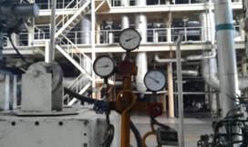
Fourth, the technical transformation of the feed pump 4.1 Pre-pump transformation Pre-pump solution Site equipment process location diagram: Front pump ----- motor --- Liquid couple - to the pump. Cavitation: When the pump is running, the liquid pressure drops along the inlet of the pump to the inlet of the impeller. At point K near the inlet of the blade, the pressure of liquid pK is the lowest. Afterwards, due to the work done by the impeller on the liquid, the liquid pressure rises quickly. When the pressure pK near the impeller blade inlet is smaller than the saturated vapor pressure pv at the liquid delivery temperature, the liquid evaporates. At the same time, the gas dissolved in the liquid escapes. They form a lot of bubbles. When the bubbles flow with the liquid to the higher pressure in the blade, the pressure of the external liquid is higher than the vaporization pressure in the bubble, the bubble recondenses and collapses to form cavities, and the surrounding liquid at an extremely high speed instantaneously. Rushing into the holes causes the liquids to collide with each other, causing a sudden increase in local pressure (some can reach several hundred atmospheres). The above-mentioned phenomena of liquid vaporization, condensation, impact, formation of high pressure, high temperature, and high frequency impact load, resulting in the combination of mechanical peeling and electrochemical corrosion damage of metal materials, are referred to as cavitation.
After communicating with field engineers, in order to prevent cavitation, they set the minimum speed at 3200 r/min in the feed pump operation. Ensure that the pre-pump must be NPSH 5.2 meters. No way to separate the front pump from the motor was taken.
4.2 Hydraulic Couplings:
(1) During frequency conversion operation, the position of the liquid coupler is opened to the maximum, and the liquid coupling acts as a coupling.
(2) Since the main oil pump is coaxial with the motor, after the frequency conversion is adopted, the oil pump pressure and oil quantity will be insufficient after the motor speed is reduced. The oil pump requires the lubricating oil pressure to be not less than 0.24 MPa, and the lubricating oil quantity shall not be less than 400 L/min. The working oil pressure is not less than 0.24 MPa, so to meet the oil supply of the oil pump, configure the oil station separately. Dismantling of the primary liquid pump, including the modification of the oil line of the oil station, the basic production and installation of the oil station, and the removal and modification of the main oil pump impeller of the fluid coupling.
(3) Configuration of the oil station: Two oil pumps (including the drive motor) are used one by one, the running pump fault trips, and the chain standby pump starts. The flow rate was 900 liters/minute, the pressure: 0.40 megapascals, the power: 4 levels 37 kilowatts, calibre: 80. The oil station must also be equipped with an electrical control box that meets the pump motor capacity and control requirements. The demand side provides the electrical power required for the electrical control box. Tank, oil temperature, oil pressure, oil detection device and other accessories, etc., the detection signal can output 4-20mA signal.
(4) When the inverter is faulty or overhauled, it is switched to the power frequency operation by the inverter bypass. At this time, it still follows the original mode of operation, with liquid coupling speed control.
Figure 8: Photo of the fluid coupling retrofit station
4.3 Design and operation of high-power inverters The main inverter components inside the high-voltage inverters are high-performance IGBTs produced by the German high-quality brand fourth-generation IGBT chips and PRIMEPACK packaging technology. The technical advantages are mainly reflected in: 4.3.1 New-Generation IGBT Features (1) The fourth-generation IGBTs improve the operating characteristics of IGBTs and make them more flexible than the third-generation IGBTs.
(2) The fourth-generation IGBTs can adapt to smaller drive resistances without generating severe voltage spikes and achieve lower switching losses than third-generation IGBTs;
(3) The temperature characteristics of the fourth-generation IGBT enhanced chip can be run at 150 °C, the maximum withstand temperature is 175 °C, while the third-generation IGBT can only operate at 125 °C, the highest tolerance is only 150 °C;
(4) The fourth-generation IGBT has the same short-circuit withstand capability as the third-generation IGBT, which can ensure the safety and reliability of the work;
(5) Compared with the second-generation third-generation IGBT, the fourth-generation IGBT has excellent performance in power cycle life, as shown in the following table:
Table 4
(6) The fourth-generation IGBTs maintain the positive temperature characteristics of the third-generation IGBTs and are easily connected in parallel.
4.3.2 Device Current Sharing Problem Due to the limited flow capacity of a single IGBT chip, high-power products often use IGBTs in parallel to increase output current capability. The IGBT itself has a positive temperature coefficient and has a self-leveling capability and is suitable for parallel connection. In order to ensure the reliability of the equipment, the components first increase the design margin factor when the capacity is calculated, which is approximately twice the margin.
The use of dynamic current sharing and static current sharing technology to reduce the impact of the saturation voltage drop Vce(sat) of the IGBT and the forward voltage drop Vf of the anti-parallel diode on the static current sharing effect; and the IGBT transconductance gfs and gate-emitter stage The influence of the threshold voltage Vge_th and the reverse recovery characteristics of anti-parallel diodes on the dynamic current sharing effect.
4.3.3 Device Heat Dissipation Problem In a high-power inverter, the heat power density is much higher than that of a conventional inverter, and the conventional heat dissipation structure cannot meet the requirement of high-density heat dissipation. For this reason, we use a special heat dissipation structure and layout design to increase the heat dissipation power density and optimize the thermal field distribution so as to avoid damage to the device caused by excessive IGBT junction temperatures.
4.3.4 High Current Electromagnetic Noise Suppression Problem When the IGBT is switched, the spike voltage generated in the busbar parasitic inductance is a major cause of IGBT damage. This voltage is proportional to the operating current, parasitic inductance, and inverse ratio to the IGBT operating time. Since the IGBT operating time changes little under different currents, the spike voltage will increase proportionally as the device current increases. The main circuit structure of IGBTs is connected in parallel to cause line inductance difference. The difference of these inductive reactances will seriously affect the dynamic operation characteristics of IGBTs. With symmetrical main circuit structure, large current noise is effectively suppressed. 5, cooling problem, high-power inverter due to inverter heat accounted for 3-4% of the rated power, so the heat is a must consider. Directly affect the stable operation of the equipment.
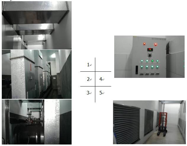
Datang Fuyang Power Plant 5.5MW feed pump frequency converter adopts the cooling method of the project using the air cooling device model: BLH-CK-260. The cooling power reaches 260KW, and the on-site environment is very clean.
Figure 9: Empty water cooling site picture
1. Inverter outlet air duct 2, Inverter outdoor air duct 3, Air-water-cooled supercharged air blower 4, Air-water-cooled power distribution control box 5, Air-cooled room air inlet 4.3.5 Inverter selected for Puyang power plant feed water pump motor and Load characteristics. Beijing Leader Huafu Electric Technology Co., Ltd. provides model: HARSVERT-VA06/600, rated capacity of 7000KVA inverter 4.3.6 DCS control transformation: The control system of the high-voltage variable-frequency speed control system is safe and reliable. Its control power adopts AC220V and DC220V, dual-way power supply, mutual backup, and realize bumpless switching to ensure the stability of the control power supply.
The frequency conversion device has a user interface with the DCS of the field distributed control system. The frequency conversion device controls the starting and stopping of the motor according to the DCS control instruction to control the rotation speed of the motor; the frequency conversion device feeds back the main status signal and fault of the frequency conversion device to the DCS through the hard connection line method. Alarm. In the existing DCS system, the control function of the feed pump frequency converter is increased.
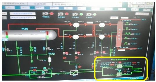
Figure 10: Screenshot of DCS screen
V. Summary of project benefits after transformation: 5.1 Summary of project effects (1) After the frequency conversion speed control system is installed, the motor can be soft-started through the inverter to improve the start-up performance of the motor and extend the service life of the motor. At the same time, the motor is greatly reduced because of the soft start. The start-up current reduces the impact of motor start-up on plant power.
(2) When the motor is running at industrial frequency, the actual operating power factor is much lower than the rated value. After the high-voltage variable frequency speed control system is used, the power factor on the power supply side can be increased to more than 0.95, which greatly reduces the absorption of reactive power and further saves the upstream. Equipment operating costs.
(3) After adopting frequency conversion regulation, energy saving can be realized by adjusting the motor rotation speed; when the rotation speed is reduced, the wear of the main equipment and corresponding auxiliary equipment such as the bearing is lighter than before, and the maintenance period and equipment operation life are extended;
(4) After adopting frequency conversion adjustment, the running current of the motor is reduced greatly, and the energy saving rate varies from 10% to 30% according to the load, which achieves the expected effect of the project.
(5) The energy-saving effect of the equipment operation is good, the temperature of the inverter's cell is stable at about 28°C, and the cooling system has a good cooling effect.
(6) The equipment has been in operation for two years and has never failed. It has never affected the production of users. The Hunan Datang Huayin Group was well received.
Datang Puyang Power Plant belongs to the peak-shaking unit. The power plant load changes greatly. The reformation project of the induced draft fan inverter is put into operation after the power plant is completed. The unit runs for about 250 days in a year.
The inverter operating data is as follows:
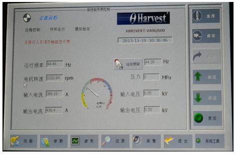
During the on-site inspection of 2013.12.1, the unit load was 200MW, and the frequency of the induced draft fan inverter was 44.39HZ. The input current is 386.19A, the output current is 436.4A, the input voltage is 6.05KV, and the output voltage is 5.55KV.
Fig. 11: Screenshot of human-machine interface (200MW load operation of inverter)
5.2 Data Analysis of Energy Saving Rate (Sources of Data, User's Report on Completion of the Project)
time
Unit load MW
Switch current A
time
Unit load
MW
Switch current A
Variable frequency operation
2012-10-30
140.5
269.6
Power frequency operation
2011-4-18
137.6
382
2012-10-31
140.9
263
2011-4-18
144.1
387
2012-10-31
140.5
267.7
2011-4-18
136.9
364
2012-10-31
139.2
275.1
2011-4-19
146.8
368
2012-11-1
140.4
279.3
2011-4-18
144.5
375
2012-11-1
140.9
291.9
2013-1-11
138.25
335.7
2012-11-1
140.4
287
2013-1-11
142
380
2013-1-11
140.2
291
2013-1-11
140.2
362
2013-1-11
141
309
2013-1-11
140.6
302
Level difference
1.8
46
9.9
51.3
average value
140.46
283.56
average value
141.98
375.2
Power factor
0.93
0.85
Energy saving rate %
17.3 %
2.2 The energy-saving effect of frequency conversion of the #1 feed pump is obvious, and it can reach 5.57% energy-saving rate under 200MW load.
time
Unit load MW
Switching current
A
time
Unit load
MW
Switching current
A
frequency conversion
2012-12-28
200
383
Power frequency
2011-4-20
200
437
2012-12-27
201.5
403
2011-4-21
200
463
2012-12-25
199
395
2011-4-21
200
459
2013-1-11
198.3
430
2013-1-11
200.5
474.1
2013-1-11
199.3
430
2013-1-11
199.5
487.6
2013-1-11
199.8
433
2013-1-11
200.4
431
2013-1-11
199.9
474.6
Level difference
3.2
50
1
56.6
average value
199.65
412.3333
200.0429
460.9
Power factor
0.95
0.9
Energy saving rate %
5.57%
After data weighted analysis, the integrated energy-saving rate of the feedwater pump is between 10% and 15%. The benefit is very obvious.
About the author: Zhang Kedong, graduated from Wuhan Vocational and Technical College in 2004. Has long been engaged in high and low voltage inverter after-sales service and pre-sales technical support work. He has served as an after-sales service engineer for the technical engineering system and an engineer for the domestic pre-sales service department of the marketing system of Beijing Leader Huafu Electric Technology Co., Ltd.
References: Yipeng. Principles and Applications of High-Voltage High-Power Inverters. Beijing: People's Posts and Telecommunications Press, 2008.
Electric Aroma Oil Diffuser,Electric Scent Diffuser,Electric Fragrance Diffuser,Electric Air Diffuser
Guangzhou Tang Mei Environmental Protection Technology Co.,Ltd , https://www.diffusermachine.com