![<?echo $_SERVER['SERVER_NAME'];?>](/template/twentyseventeen/skin/images/header.jpg)
Voltage transformer insulation test method
I. Test items for voltage transformers Voltage transformers for voltage classes of 20kV and below use dry solid sandwich insulation. However, there are also some oil-immersed sandwich insulation structures for indoor use. For their insulation tests and current transformers are basically the same, but depending on the actual needs of the site, sometimes increased induction voltage test.
Voltage transformers with voltage ratings of 35 to 66 kV should be tested for insulation resistance, AC withstand voltage (cascade insulation cannot be performed), inductive withstand voltage, and dielectric loss tangent (tan δ).
For voltage transformers with voltage ratings above 66kV, analytical tests for dissolved gases in insulating oils should also be added.
For each of the above test methods, reference may be made to the relevant items of the transformer test and the insulating oil test. Only the measurement of the tan δ value of the tandem-type voltage transformer is subject to additional wiring in order to obtain a correct judgment.
Second, the tanδ value of the cascade voltage transformer measurement method There are high voltage standard capacitor self excitation method, capacitive voltage transformer test method, low voltage standard capacitor self excitation method, end shield method. According to the actual situation of the site, select the measurement method.
1. High-voltage standard capacitor self-excited method Using high-voltage AC bridge, high-voltage standard capacitor self-excited method to measure the tan δ value of cascade-type voltage transformer wiring as shown in Figure 1-1. In the figure, AX is the outgoing end of the two-element iron core in series with the high-voltage side winding, ax is the outgoing end of the low-voltage side winding, and ad-xd is the outgoing end of the auxiliary winding on the low-voltage side. The voltage transformer itself is used as the test transformer in the figure, and the capacitance of the bushing and winding to ground is taken as Cx. The voltage distribution of this line is consistent with that of the voltage transformer. Therefore, the large capacity near the low-voltage side of the high-voltage side winding is avoided, resulting in the disadvantage of mainly reflecting the medium loss at the low-pressure side. If a higher voltage standard capacitor can be used, the self-excited voltage can reach the rated value, which is closer to reality. Such as the domestic standard 250kV sulfur hexafluoride capacitor, to meet the 110kV and 220kV voltage transformer under the operating voltage measured by the self-excited tanδ test. The test method and method of measuring tan δ using the QS1 bridge diagonal wiring method are exactly the same. Since the bridge body is at the low voltage end, the standard capacitor can be selected at a higher voltage level to meet the measurement requirements of the voltage transformer. 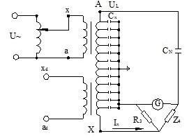
Figure 1-1 Measurement of tan δ value using high voltage standard capacitor self-excitation method 2. Low-voltage standard capacitor self-excited method As shown in Figure 1-2, the standard arm in the QS1 type bridge body is used as the standard arm of the bridge, and the tandem type The transformer performs a self-excited measurement of the tan δ value. 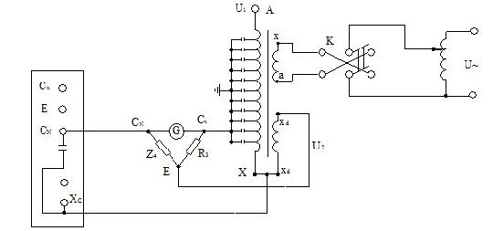
Figure 1-2 Measurement of tan δ value using self-excitation method of low-voltage standard capacitor As can be seen from Figure 1-2, the power supply of the bridge is taken from the voltage induced on the terminal of the auxiliary winding, and the voltage on the standard capacitor arm is low. The load of the auxiliary windings is very small, and the U1 and U2 vectors are basically coincident. Experience shows that the angular difference between them is negligible.
Regardless of whether the self-excitation method using a high-voltage standard capacitor or the self-excitation method using a low-voltage standard capacitor is used, when measuring the value of the cascade-type transformer, the interference of a strong electric field is still not avoided. The sources of interference are an external electric field from the high voltage side of the transformer (a nearby high voltage device) and a secondary excitation system. The former can be eliminated by means of high voltage shielding. The specific method refers to the test of the transformer. The latter can place the grounding point of the voltage regulator as close to the sliding contact as possible. In addition, the phase of the self-excited power supply can also be exchanged to minimize the interference.
3. End shield method As shown in Figure 1-3, the QS1 high voltage bridge can also be used for measurement, and the high voltage test transformer B is required to excitate the high voltage side of the tested voltage transformer and supply the bridge power supply. The low-voltage terminal is grounded, and the low-voltage winding is also at a lower potential, which basically avoids the influence of the small casing due to moisture and dirt on the measured value. It can be seen that the terminal shielding method can only measure the tan δ value of the high voltage winding portion directly coupled with the low voltage winding and the auxiliary winding. The end shield method also has the interference problem between the power system and the external electric field, and the preventive measures are the same as the self-excitation method. 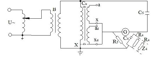
Figure 1-3 Measurement of tan δ value using terminal shielding method 4. Test method for capacitive voltage transformer Capacitance voltage transformer wiring is shown in Figure 1-4. It consists of a capacitor voltage divider (including main capacitor C1, voltage divider capacitor). C2) Intermediate transformer (namely middle transformer YH), resonance reactor L1, carrier impedance device L2 and damping reactor R. 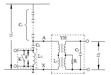
Figure 1-4 Capacitor Voltage Transformer Wiring Diagram
G—protection gap; K—break switch The test of the dielectric loss angle tan δ can be divided into single element tests. For example, the capacitor can be tested according to the requirements of the power capacitor; for the intermediate transformer, the optional “self-excitation method†or “end-shielding method†can obtain effective results.
Chaff Cutter,Chaff Cutter Machine,Electric Chaff Cutter Machine,Electric Chaff Cutter
Shuangfeng Nongjiabao Machinery Technology Co., Ltd , http://www.starchmachine.nl