![<?echo $_SERVER['SERVER_NAME'];?>](/template/twentyseventeen/skin/images/header.jpg)
Because of its small size, strong anti-interference ability, high reliability, wide application range, and low price, the programmable logic controller (PLC) has been widely used in the automatic control of small and medium industrial equipment. Thermal power plant auxiliary systems, such as ash removal systems, make-up water treatment systems, condensate polishing systems, wastewater treatment systems, and coal transportation systems, are also commonly used PLC control technology.
This article mainly introduces the control system based on PC and PLC developed for Huaneng Jinggangshan Power Plant's hydraulic ash removal system. The system has the advantages of simple programming, reliable operation, convenient use and good portability.
First, the control system
Ash removal system process shown in Figure 1. System control requirements should have system switching, automatic program control, and group or single-group operation functions. In addition, functions such as skipping, interruption, and latching should also be available.
(1) Control the operation of the electric air lock, electric three-way, electric agitator and entrance electric door under the ash hopper of each electric field is controlled by the PLC program; the speed of the three-step mortar pump is automatically controlled by the PLC, when the mortar tank liquid level is low At the same time, the speed of the mortar pump is blocked; the operation of the three-stage mortar pump and the inlet and outlet valves is automatically switched by the PLC according to the set conditions; the operation of the high and Low Pressure pumps and related valves is controlled by the PLC program.
(2) Interlock protection When the operation pump accident of the ash removal system is tripped, the backup pump is started automatically and its outlet electric gate is closed. When there is a problem with the first stage of the three-stage pump, the other two-stage pump is closed and an accident alarm is issued.
Second, the hardware configuration
Two industrial control computers (industrial computers) are used for monitoring to realize dual-system hot backup of the monitoring system. Each industrial control machine can control the ash removal system of two furnaces. Two sets of furnaces are set up independently of each other. The PLC CPU modules and communication modules of each furnace are dual-system hot backups to ensure the reliable operation of the ash removal system. Detailed configuration is shown in Figure 2.
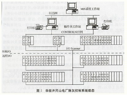
2.1 Network System
RSlinx is used for communication between the PLC's CPU and operator workstations. RSlinx is a communication software based on the American AB Corporation's CONTROL-NET communication protocol. Between the operator workstation and the main control room workstation through the power plant MIS (management information system) network communication, MIS network communication protocol is TCP / IP protocol, in line with the OSI 7 layer model structure, consistent with the commonly used Internet protocols. Therefore, the operator workstation is organically linked with the Internet, and as long as there is advanced administrator authority, the monitoring screen information can be viewed anywhere on the Internet.
2.2 Monitoring Computer
IPC's CPU and memory configuration should be relatively high, because the operator workstation not only has to communicate with the PLC CPU in real time, but also exchange data with the IPC workstation. If the configuration is low, it will often crash, leading to serious consequences. 2 Advantech IPCs.
The CONTROLNET network interface card KTC (X) of AB Company is installed in the PLC slot of each IPC and is used to compose the CONTROLNET network with the CPU of the PLC. The communication medium of the network is a copper shaft cable.
In the programming phase, an industrial computer is installed with AB company's programming software RSLogix5 to write ladder diagrams, set parameters for the PLC, scan the program I/O, and upload and download ladder programs that have been programmed. In the operation stage, the monitoring software RS-View32 of AB company is installed on the two monitoring computers as the operator workstations. It can display the operation information of the ash removal system and monitor and control the operation of the ash removal system; Alarm display and voice prompts for equipment failure; display real-time curves, historical trends, and report printing functions. Any one monitoring computer can complete the monitoring function of two furnaces. When one of the monitoring computers fails, the other machine can operate two furnaces without any influence.
2.3 PLC system
The PLC adopts the PLC-5 series of AB Corporation. From the aspects of reliability, special control functions, anti-jamming capability, scanning speed, host computer interface and remote communication functions, and computer networking and various software functions, the controller is There are certain advantages. The main modules of the system are selected as follows.
(1) The CPU module is 1785-L80C. The CPU module has a key switch that has three modes: RUN mode, PROG mode, and REM mode. In the operation mode, data files cannot be created or deleted, output is valid, and I/O can be forced; in the programming mode, ladder files can be created, modified, and deleted, but output is prohibited; when the key is in remote mode, Remote programming, remote testing, and remote operating state changes via software.
(2) Power modules are 1771-P6S, 1771-P7. The former is a 220V (AC), 8A power supply installed in the local PLC cabinet; the latter is a 220V (AC), 16A power supply installed in the remote I/O cabinet.
(3) The adapter modules are 1785-BCM and 1771-ASB. The former is a hot standby communication module of the CPU; the latter is a remote I/O adapter module.
(4) Base modules are 1771-A1B (4-slot rack) and 1771-A4B (16-slot rack).
(5) The switch input module is 1771-IMD (220V (AC), 16 inputs).
(6) Switch output module is 1771-OW16B (16 relay output module).
(7) The analog input module is 1771-IFE (12-bit, 8-way differential/16-channel single-ended) and requires a jumper before it is inserted into the rack.
(8) The analog output module is 1771-OFE2 (12-bit, 4-channel, current-type) and jumpers are required before insertion into the rack.
2.4 Electrical cabinets and local instruments
There are 6 electrical cabinets, including 1 power cabinet, 1 PLC cabinet, 1 local pump control cabinet, 1 pump room remote control cabinet, 2 ash bucket remote control cabinets (1 and 2 each 1 station). In order to ensure the stable operation of the system, the power cabinet is equipped with 2 uninterruptible power supplies (UPS, Hills, Inc.), 1 power supply for the monitoring system, 1 for the local instrument supply; PLC cabinet is equipped with the PLC's CPU module; The three-stage pump local control cabinet and PLC cabinet are discharged into the control room, and the pump room remote control cabinet and the ash bucket remote control cabinet are placed under the pump room and the ash bucket.
Local instruments include ultrasonic level measuring instruments, temperature controllers, pressure controllers, spring tube diaphragm pressure gauges, and radio frequency admittance level meters.
Third, software design
The principle of software design is: full opening, minimizing manual intervention and operation during operation, system parameters and process parameters online adjustable, power-off self-protection and power-on self-recovery, etc., so as not to crash during operation, signal acquisition and display interference.
The software of the system mainly includes 3 parts: Communication software, upper computer monitoring software and lower computer software. The upper and lower computer software were written by AB company's RSView32 monitoring software and RSLogix5 programming software, respectively.
3.1 Communication Software
The first step is to install AB company's communication software RSLink (based on the CONTROLNET protocol) on the operator workstation IPC so as to detect the PLC CPU and other operator workstations and then number the workstations.
3.2 PC monitoring software
3.2.1 Key Features of RSView32 Monitoring Software
(1) Tag database can be reused RSView32 can be used to conveniently browse the funeral tag database and select the required ladder logic tag from Allen-Bradley PLC or SIC database without importing the entire database.
(2) graphics and animation RSView32 supports many standard graphics formats, so you can use the original Windows metafile, AutoCAD graphics files, and transfer them to the RSView32 display without having to re-create them.
(3) Powerful graphics library RSView32 comes with hundreds of graphic files, which can be updated to the latest online library in a limited time.
(4) Easy to expand and update It is easy to upgrade the RSView32 software to a maximum of 100,000 tags.
(5) Additional Resource Toolkit RSView32 is also loaded with a resource toolkit that provides efficient tools. Including the project document editor, project transfer wizard, palette customization tools.
3.2.2 main functions implemented by this control system
(1) Real-time operating parameter monitoring Each monitoring system collects actual operating condition parameters and can display the real-time operating conditions of the system in the form of graphs and reports.
(2) Equipment failure and analog over-limit alarm When equipment failure or analog over-limit occurs, the production monitoring and management network synchronously displays the name of the faulty equipment, and can realize voice alarm and real-time printing fault function. The server stores the fault information in the fault information database for later statistical analysis.
(3) Historical data query The above production real-time monitoring data can be stored in the production real-time data historical database, which can realize historical echo and historical trend analysis, and can be comprehensively analyzed using histograms, pie charts and the like.
(4) The recording function can record the operation, alarm, and data in the database for later query. For example, it can check every step of the previous day's operation by all operators to record all the values ​​of the instrument after the operation.
(5) The use of sub-privilege uses different functions of authority according to the functions of the personnel and performs their duties. The engineer can use the modification authority to adjust the program and parameters in time; the operator has the operation authority and can operate the control system; the person without the authority can only monitor and cannot control.
3.3 Lower computer programming software
The flow of application software development using RSLogix5 software is as follows:
(1) Setting the CPU type of the PLC After the RSLink communication software is installed, the CPU of the PLC can be detected. After the correct selection of the model, the communication green light on the CPU module will be displayed normally.
(2) Scanning the remote station The CPU module and the remote station's adapter module are connected via a twisted pair cable. The automatic scan function can be used to find the adapter module at the remote site.
(3) Configure the modules on the remote station to configure each module on the rack one by one. The switch module does not require special configuration, but the analog modules need to be configured one by one. For example, the (4 to 20) mA type must be selected.
(4) Compiling Ladder Diagram The ladder diagram is the core software for the entire control system. It has large programs and complicated logic. It needs to be programmed according to the process requirements to achieve the requirements of interlocking, locking, soft hand operation, grouping, semi-automatic, automatic and other requirements. .
(5) After the download program program is checked, it is downloaded from the industrial control computer to the CPU memory of the PLC.
Fourth, the conclusion
The Jinggangshan Power Plant's ash control system was put into operation in early 2000. For more than four years, the system has been operating reliably, with complete functions, easy operation, and low maintenance. It has been well received by users and has accumulated a wide range of applications for PLC control systems in power plants. experience.
The energy saving of blow molding machines can be divided into two parts: one is the power part and the other is the heating part.
Energy-saving part of the power: Most inverters are used. The energy-saving method is to save the remaining energy of the motor. For example, the actual power of the motor is 50Hz, and you actually only need 30Hz in production to produce enough. The extra energy consumption is in vain. Wasted, the frequency converter is to change the power output of the motor to save energy.
Heating part of the energy: Most of the heating part of the energy-saving is the use of electromagnetic heaters, energy saving rate is about 30% -70% of the old resistor ring.
1. Compared with the resistance heating, the electromagnetic heater has a layer of insulation and the thermal energy utilization increases.
2. Compared with the resistance heating, the electromagnetic heater directly acts on the heating of the material tube, which reduces the loss of heat transfer heat energy.
3. Compared with resistance heating, the heating rate of the electromagnetic heater is more than a quarter faster, reducing the heating time.
4. Compared with the resistance heating, the heating speed of the electromagnetic heater is fast, and the production efficiency is improved, so that the motor is in a saturated state, which reduces the power consumption caused by high power and low demand.

Plastic Blow Molding Machine,Plastic Blowing Machine,Molding Machine For Making Plastic Bottle
Shandong Qufu Xingbang Heavy Equipment Co., Ltd. , http://wwww.chinaxingbangheavyindustry.com